FIT
Abnormal connector fit
A mating connector may feel unusually tight, inconsistent, or unable to seat normally because the female outer-contact geometry is no longer round.
A mechanically damaged 4.3-10 connector can remove an otherwise serviceable remote radio unit from circulation. Port Reformer™ provides qualified RF technicians with a controlled method to restore suitable out-of-round female port geometry without replacing the connector, opening the RF cavity, or retuning the RRU.
RRU failures are not always internal. Shipping damage, impact, installation damage, or over-tightening can deform the external 4.3-10 female interface while the radio's internal RF path remains serviceable.
A mating connector may feel unusually tight, inconsistent, or unable to seat normally because the female outer-contact geometry is no longer round.
Deformation can reduce consistent mechanical engagement and contact uniformity, contributing to changes in sweep, return loss, VSWR, or PIM behavior.
A small external defect can lead to connector replacement, cavity disassembly, retuning, shipping, extended cycle time, replacement demand, or scrap.
The NGMN Alliance identified the 4.3-10 interface as a compact connector system suited to radio units, antennas, and antenna-line devices, with improved PIM performance and higher connector density compared with the legacy 7-16 format.
Its design uses spring-loaded lateral contact at the outer conductor. Contact pressure is established when the connector interfaces are engaged, while the coupling mechanism primarily secures the connection. That design context helps explain why the condition, roundness, and contact uniformity of a damaged female port matter during RRU diagnosis and repair.
Read the NGMN 4.3-10 RF Connector Migration Strategies white paper
NGMN is an independent industry organization and is not affiliated with or endorsing Port Reformer™. The reference is provided for connector-design context.
This process is intentionally narrow: it addresses suitable external connector deformation, not every condition that can cause an RRU to fail inspection or RF testing.
Compatible 4.3-10 female RF interfaces are used across remote radio units and supporting wireless infrastructure from major telecom equipment manufacturers. Potential applications may include equipment from Ericsson, Nokia, Samsung, Huawei, CommScope, and other OEMs that use the standard 4.3-10 interface.
Compatibility is determined by the connector interface, the condition of the damaged port, and the surrounding equipment geometry—not by brand alone. A radio or RF component should only be treated when its 4.3-10 female port is mechanically suitable, the guide collar can engage correctly, and the equipment owner’s inspection and RF acceptance requirements can be followed.
Manufacturer names and trademarks are the property of their respective owners. Port Reformer™ is an independent product and is not affiliated with, authorized by, sponsored by, or endorsed by any manufacturer listed above. Listing a manufacturer does not mean every model from that manufacturer is compatible.
The correct disposition depends on the type and severity of damage. Port reforming adds a controlled recovery option before a radio is automatically routed to a higher-cost path.
| Repair path | Typical work involved | Operational consideration |
|---|---|---|
| Replace or scrap the RRU | Remove the asset from service, source replacement inventory, ship, administer the return, or dispose of the unit. | Fastest disposition in some programs, but may sacrifice an otherwise serviceable and valuable radio. |
| Replace the RF connector | Disassemble the radio or cavity, remove and install hardware, inspect the RF path, reassemble, retune, and complete full acceptance testing. | Appropriate for severe or non-reformable damage, but requires specialized capability, parts, labor, and cycle time. |
| Reform the existing 4.3-10 port | Inspect and clean, install the guide collar, advance the precision mandrel with controlled hand pressure, remove, clean, gauge, and RF-test. | Preserves the existing connector and avoids cavity entry when the RRU port is a suitable candidate. |
Port Reformer™ uses a guided, non-cutting mechanical process. It is intended for qualified RF personnel working under an approved repair or evaluation procedure.
Confirm that the port is an appropriate candidate. Remove accessible loose debris with a clean, dry foam swab and inspect the center conductor, plating, threads, and connector body.
Start the collar by hand and keep it square to the connector. The collar creates a controlled alignment path and helps prevent off-axis loading of the mandrel.
Advance the precision mandrel through the guide collar using slow, steady hand-tool pressure. Do not use impact tools, lubricant, or uncontrolled force.
Remove the tool, clean the connector, verify the geometry with the Go/No-Go gauge, and complete the sweep, return loss, VSWR, PIM, or other acceptance testing required by the program.
This page is an overview, not a substitute for the published Port Reformer instructions or the customer's approved RRU repair procedure.
Port Reformer has been used across hundreds of ports in a high-volume telecom repair environment. Successfully reformed ports have shown improved connector fit and repeatability, with VSWR and PIM improvement observed in applicable cases.
Restores suitable out-of-round external port geometry without intentionally removing connector material.
Supports before-and-after comparison using the RRU repair program's required sweep, VSWR, return loss, or PIM limits.
Creates a recovery path for radios that might otherwise be routed to connector replacement, higher-cost repair, or scrap.
Results depend on damage type, severity, plating condition, center-conductor integrity, equipment design, and test criteria. No result is guaranteed.
Visual comparison can help document the mechanical repair, but final RRU acceptance should be based on the complete inspection and RF test requirements of the carrier or repair program.
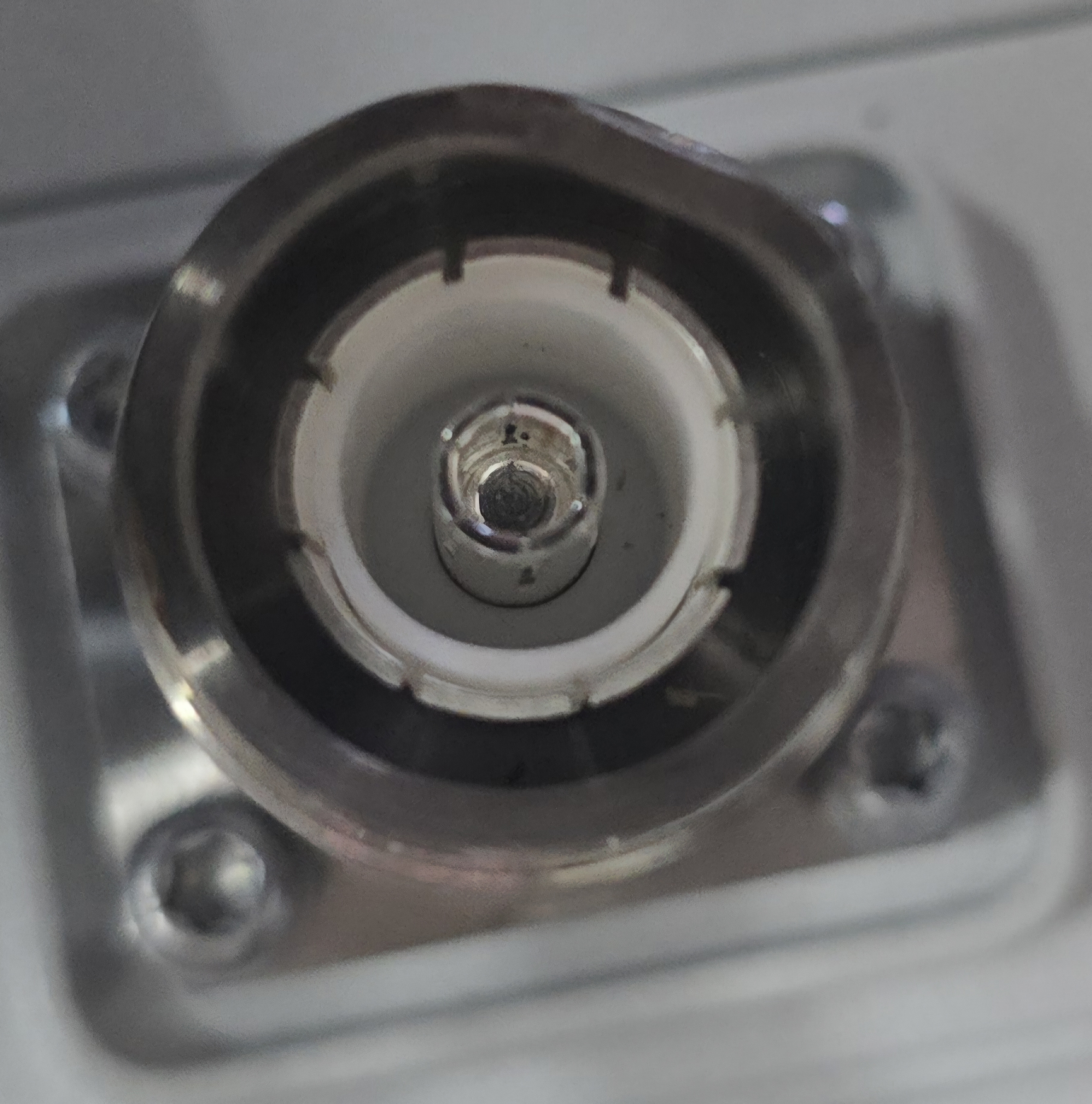
Visible deformation at the 4.3-10 female interface can compromise normal connector fit, repeatability, and contact uniformity.
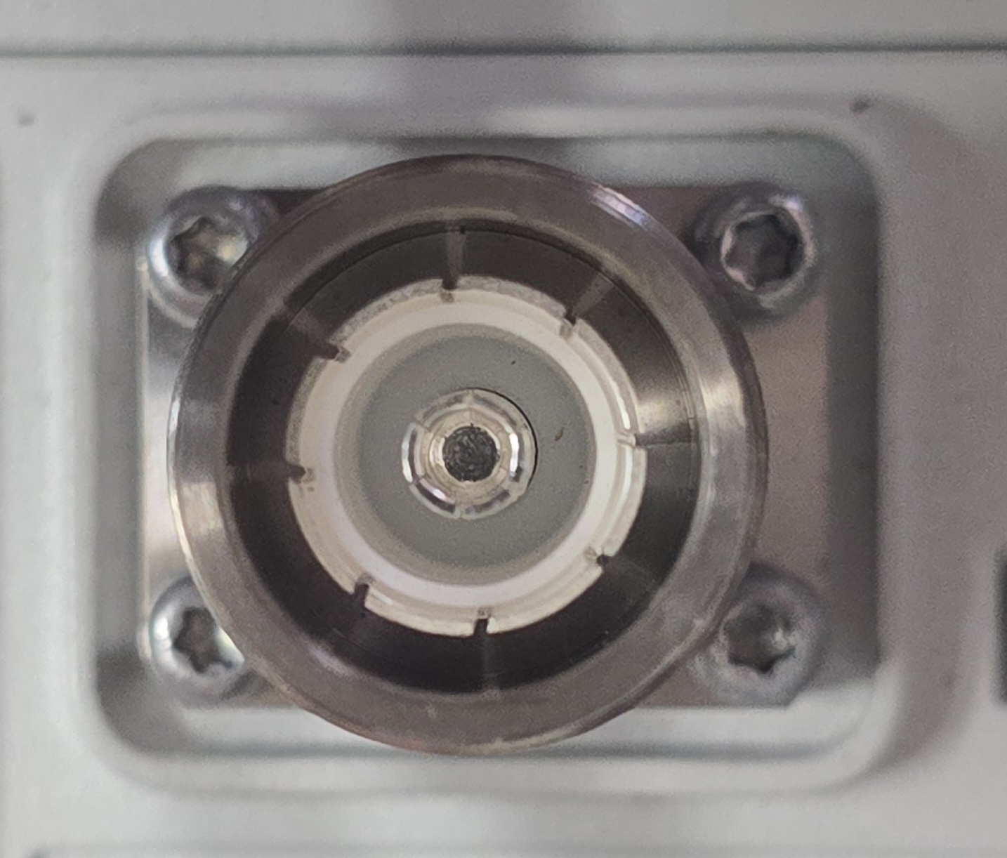
The restored external geometry supports normal mating-interface engagement before final mechanical and RF acceptance testing.
Images are for visual demonstration. Final acceptance remains the responsibility of the customer and must follow applicable safety, mechanical, and RF criteria.
Common questions from repair labs, carriers, field teams, and asset-recovery programs evaluating 4.3-10 connector restoration.
It is designed for mechanically suitable damaged or out-of-round 4.3-10 female ports on remote radio units. It does not repair unrelated internal electronic, optical, software, PA, power, or RF-module failures.
The process is performed at the external connector interface and is designed to avoid opening the RF cavity, replacing the connector, or retuning the radio when the port is an appropriate candidate.
A deformed interface can affect fit, contact uniformity, and repeatability. In lab use, VSWR and PIM improvement has been observed after successful restoration, but the measured result depends on the actual failure mechanism and the condition of the complete RF path.
Verification should include visual inspection, connector-fit or Go/No-Go gauging, and any sweep, return loss, VSWR, PIM, or other testing required by the carrier or repair program.
No. Cracked, split, severely crushed, unstable, heavily corroded, or center-conductor-damaged ports should be rejected from the reforming process and routed to an appropriate repair or replacement path.
No. Compatibility is based on the specific 4.3-10 female connector interface, surrounding geometry, and damage condition—not the manufacturer name alone. Each model and damaged port must be inspected before use and verified against the equipment owner's mechanical and RF acceptance requirements.
No. The same controlled 4.3-10 female port restoration concept may also apply to mechanically suitable ports on antennas, TMAs, filters, combiners, and DAS equipment, subject to the equipment owner's approved repair and acceptance criteria.
Send sample units, damaged-port photos, equipment types, or program requirements to discuss a controlled evaluation. A strong evaluation includes candidate screening, before-and-after documentation, mechanical gauging, and applicable RF test results.